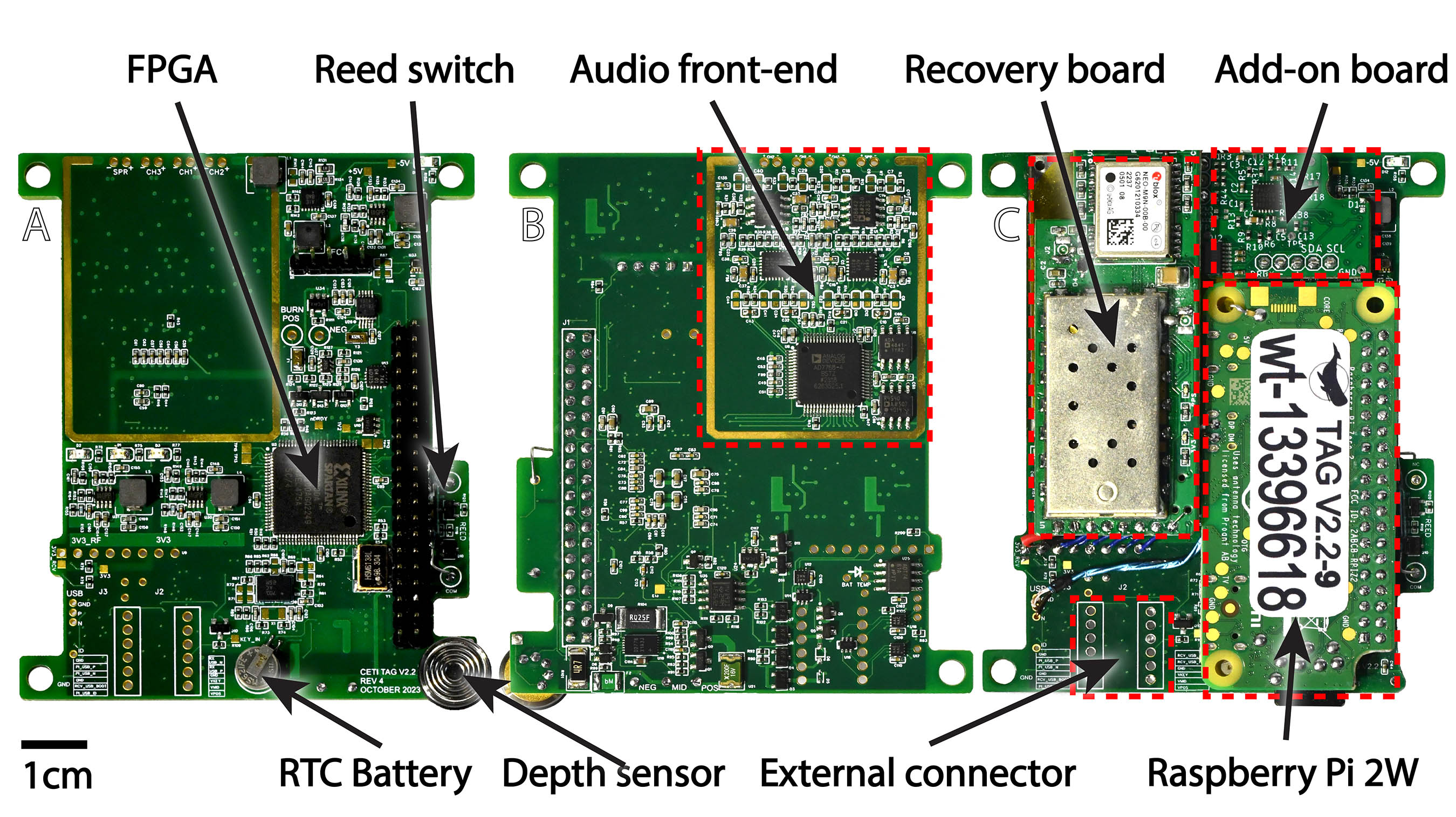
The CETI Tag consists of a single-board computer (Zero 2 W, Raspberry Pi Ltd, Cambridge,
England, UK) mounted on a custom six-layer PCB as shown above. This PCB features a
four-channel digital audio recording system along with a battery management system (BMS),
real-time clock (RTC) to provide second-accurate timing across reboots when network communication
is not available, a pressure sensor, temperature sensors, an IMU, an ambient light sensor,
the burnwire release system, and a field-programmable gate array (FPGA).
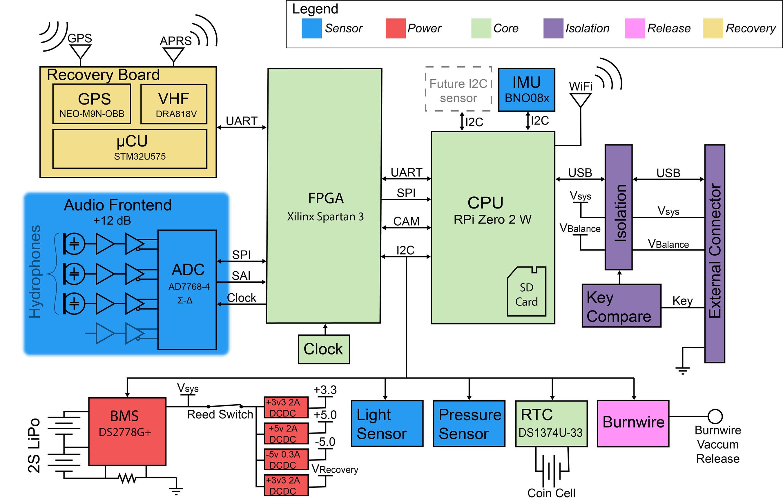
A system-level view of how these various parts are connected and how they communicate with
each other is shown below.
Two grounded metal shields encapsulate the audio section of the main board to shield
the sensative analog electronics from stray RF noise from the digital sections of the
systems.
The CETI Tag’s recovery board features two dipole antennae that are mounted at the back of the
tag such that they protrude out of the water when the tag is floating. Both antennae are simple dipoles
constructed from steal cable. The antenna for receiving GPS is designed to be a 1/4 wavelength (4.6725 cm)
at 1.57542 GHz. The antenna for receiving VHF is designed to be 1/8 wavelength (25.97 cm) at the common
APRS frequency in Dominica of 150.05 MHz.
28 AWG coax cable runs from the recovery board potted inside the tag, through a channel in the
syntactic foam to these antennae. Solder seal connectors are used electrically connect the coax core to the
dipole antenna. The entire antenna is encased in 1/16” marine grade heatshrink, and UV curable epoxy
is used to seal the any seams at the ends of the heatshrink.
The tag is designed to facilitate adding new functionality by creating daughter boards
and launching new threads within the main program. One current example of this is the recovery board,
which is a daughter board that handles GPS and APRS communication.