An exploded view of the components in the tag is shown below. To mold this epoxy and house all tag components, top and bottom halves of the shell are 3D-printed in VeroClear on a PolyJet printer (Object Scholar, Stratasys, Eden Prairie, MN, USA).
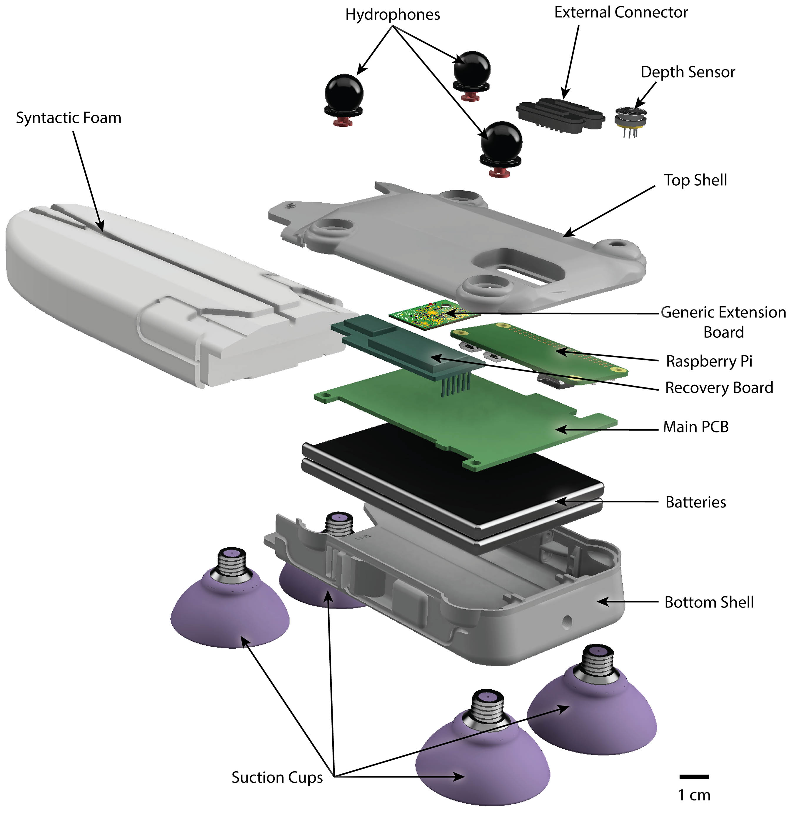
An exploded view of the components in the tag is shown below. To mold this epoxy and house all tag components, top and bottom halves of the shell are 3D-printed in VeroClear on a PolyJet printer (Object Scholar, Stratasys, Eden Prairie, MN, USA).
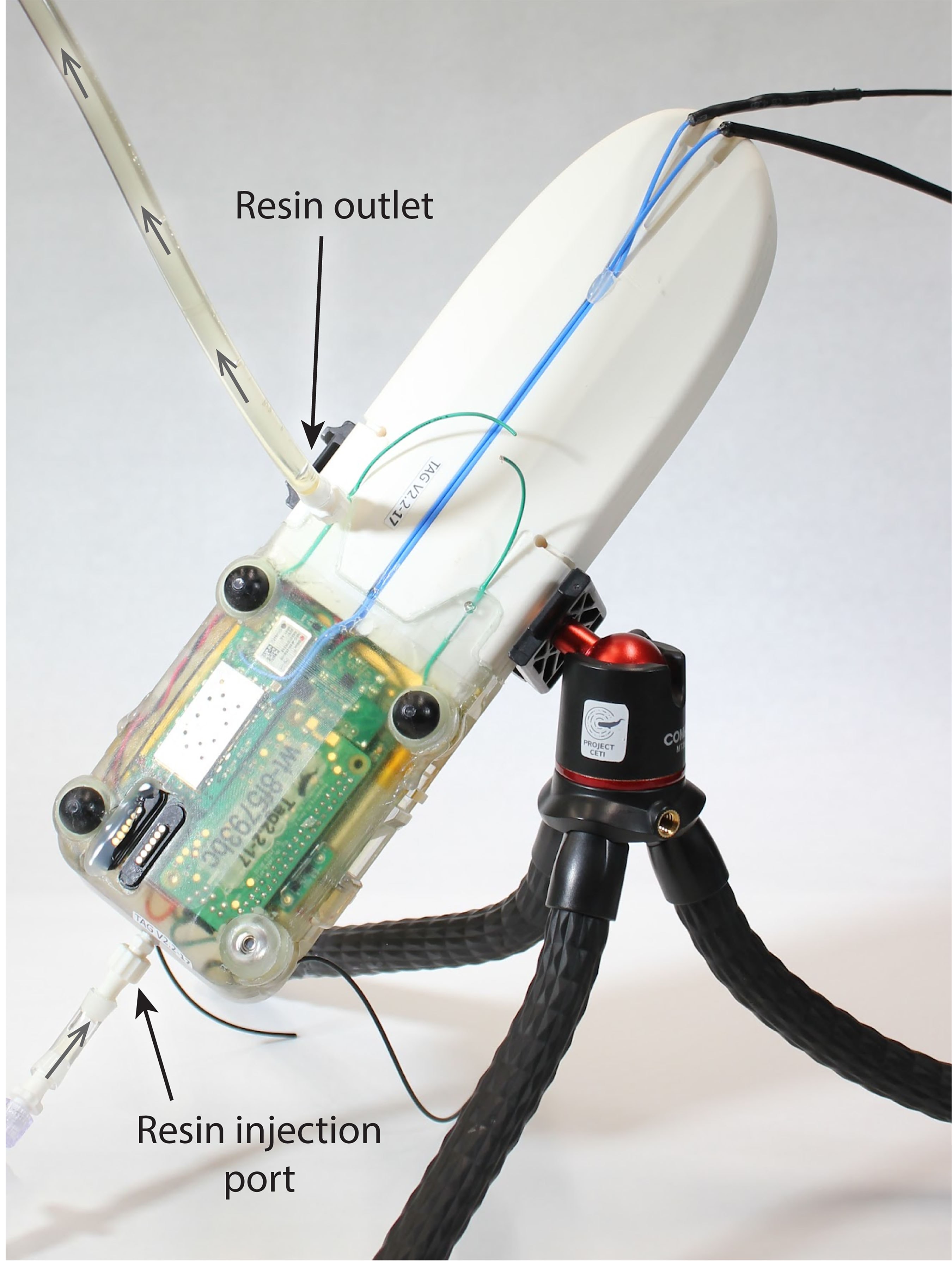
To manufacture the tag, the bottom shell is first populated with batteries and with electronics and pneumatic tubing that constitute the burnwire system for programmatically releasing tag suction. The top shell is populated with the hydrophones, depth sensor, external connector, and PCBs. The top and bottom shells are then soldered together to connect the batteries and burnwire components to the main PCB. The shells are sealed using epoxy fairing compound (TotalFair, TotalBoat, Bristol, RI, USA). After curing completes, the syntactic foam is inserted into the shell assembly and sealed with epoxy fairing compound. Finally, the tag is potted by injecting translucent epoxy (832C, MG Chemicals, Ontario, Canada) via luer lock inserts at the top and bottom of the sealed tag. The injection process is shown below, where the tag is filled with resin from the bottom to the top. The feeding inlet nozzle is driven by a dual-cartridge epoxy gun connected to a static mixing nozzle.
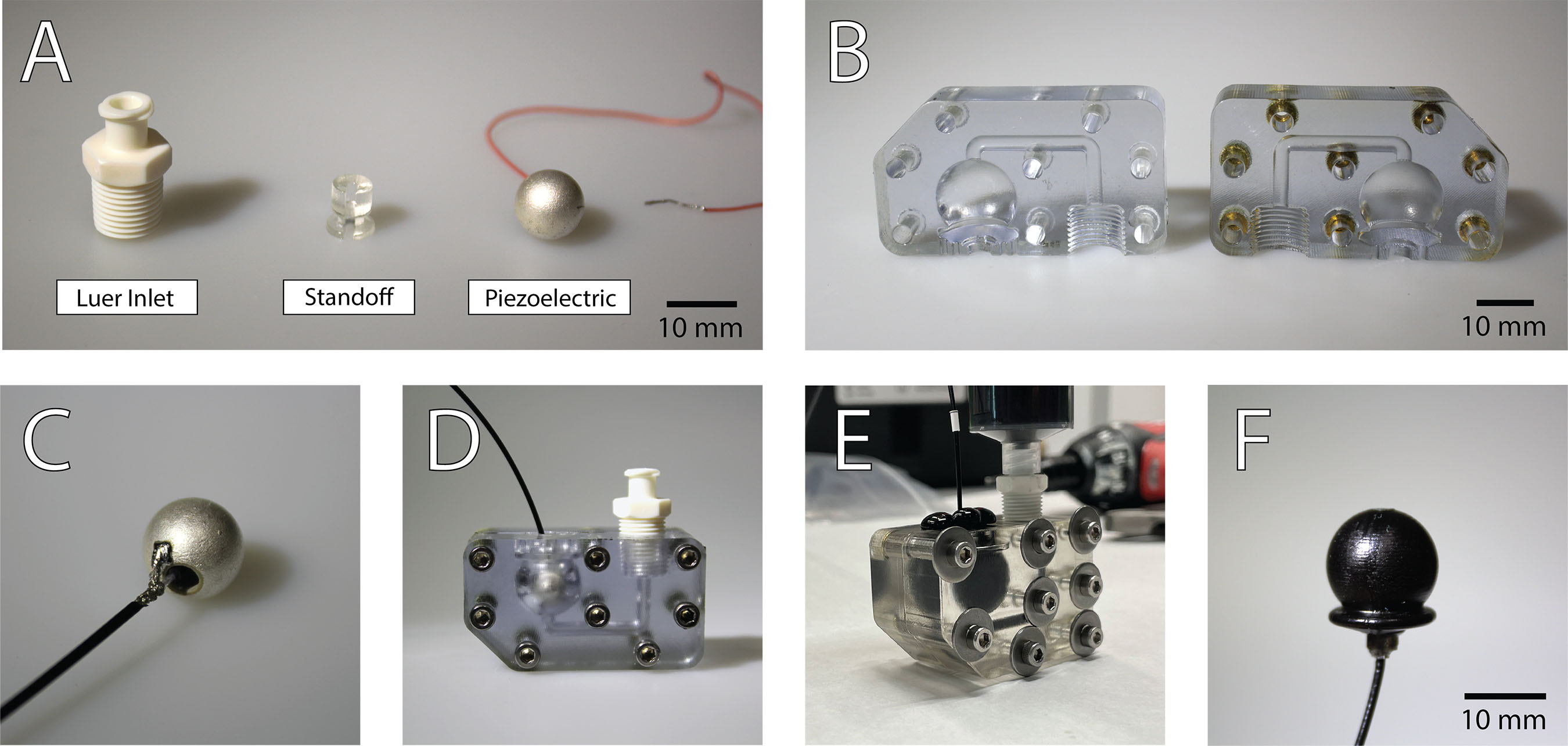
The above image summarizes the manufacturing process. A coaxial shielded cable is soldered on one end to the piezoelectric element (A) (PZT5A, Piezo Hanna, Xianning, Hubei Province, China). A 3D-printed standoff is glued to the base of the sphere to protect the wire and interface with the rest of the tag (B). Hydrophone molds were 3D-printed on a PolyJet in VeroClear and then heated at 60°C for 12 hours to prevent contamination during the curing process [3]. The molds were sprayed with a silicon release agent (Ease Release 200, Mann Release Technologies, Macungie, PA, USA) for easy removal after curing (C). Molds were assembled with the piezoelectric sphere inside and a luer lock interface for injection (D). Acoustically transparent rubber (PR-1547 potting compound, PPG Industries, Pittsburgh, PA, USA) part A was heated at 100° C for 30 minutes to decrystalize. Parts A and B were combined at a ratio of 32:100 by weight using a planetary centrifugal mixer (ARE-310, Thinky Mixer, Laguna Hills, CA, USA) (E) and transferred to a 50mL luer lock syringe. Each hydrophone mold was injected until rubber flowed out of the top (F). Caps were secured to the inlets and the molds were placed in a vacuum chamber at -10 psi for one minute to remove air bubbles. More rubber was injected until all bubbles were removed. The hydrophones were cured in a pressure oven at 550 kPa and 80° C for 8 hours.
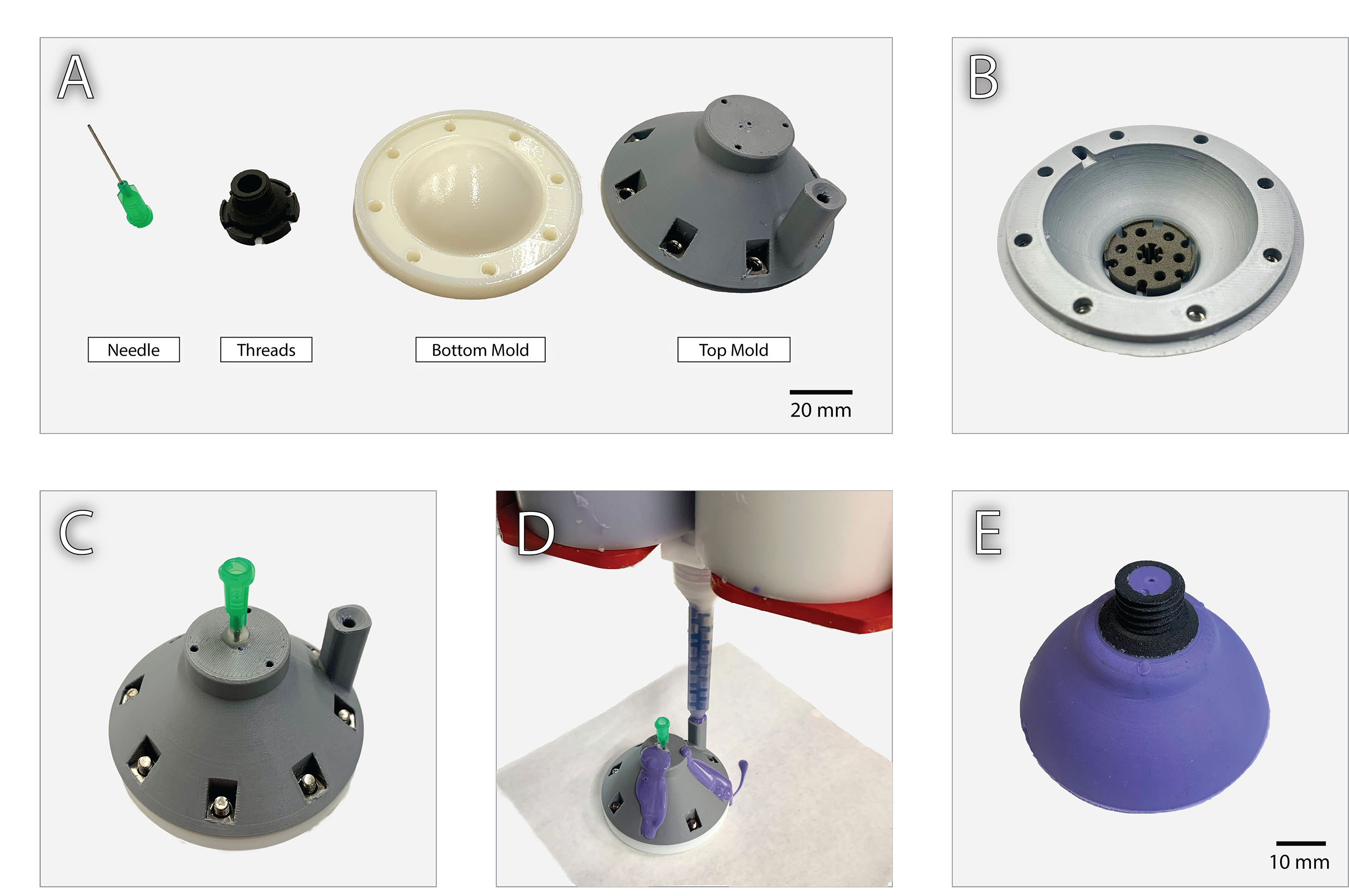
The above image shows the manufacturing process for the suction cups. The bottom mold is 3D printed in VeroWhite on a PolyJet to create a smooth surface finish on the inner face of the suction cup. This is essential to suction cup performance. The top mold is made out of Polylactic Acid(PLA) by using a Fused Deposition Modeling (FDM) 3D printer (MK3, Prusa, Czech Republic). The embedded piece is 3D printed in nylon on a Selective Laser Sintering (SLS) printer (Fuse, FormLabs, Somerville MA, USA). The top and bottom molds were sprayed with a silicon release agent (Ease Release 200, Mann Release Technologies, Macungie, PA, USA). The embedded component is threaded into the top mold and the two-piece mold is sealed with screws (B). A stainless steel 21-gauge syringe needle (75165A681, McMaster-Carr, Elmhurst, IL, USA) is inserted into the mold through a hole in the top and secured with hot glue (C). The molds were injected with a two-part silicon rubber (Smooth-Sil 945, Smooth-On, Macungie, PA, USA) using a static mixing nozzle (Optimixer 33, Nordson, Westlake, OH, USA) until excess flowed out the exit holes (D). The suction cups were cured in a pressure oven at 550 kPa and 50°C for two hours.
The CETI Tag’s recovery board features two dipole antennae that are mounted at the back of the
tag such that they protrude out of the water when the tag is floating. Both antennae are simple dipoles
constructed from steal cable. The antenna for receiving GPS is designed to be a 1/4 wavelength (4.6725 cm)
at 1.57542 GHz. The antenna for receiving VHF is designed to be 1/8 wavelength (25.97 cm) at the common
APRS frequency in Dominica of 150.05 MHz.
28 AWG coax cable runs from the recovery board potted inside the tag, through a channel in the
syntactic foam to these antennae. Solder seal connectors are used electrically connect the coax core to the
dipole antenna. The entire antenna is encased in 1/16” marine grade heatshrink, and UV curable epoxy
is used to seal the any seams at the ends of the heatshrink.
The tag is designed to facilitate adding new functionality by creating daughter boards and launching new threads within the main program. One current example of this is the recovery board, which is a daughter board that handles GPS and APRS communication.